
 Nederlands
Blog / Controller
Posted on 1 June 2013 at 12:09 am (CET)
Category: Controller, Parts
Posted on 1 June 2013 at 12:09 am (CET)
Category: Controller, Parts
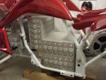
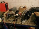
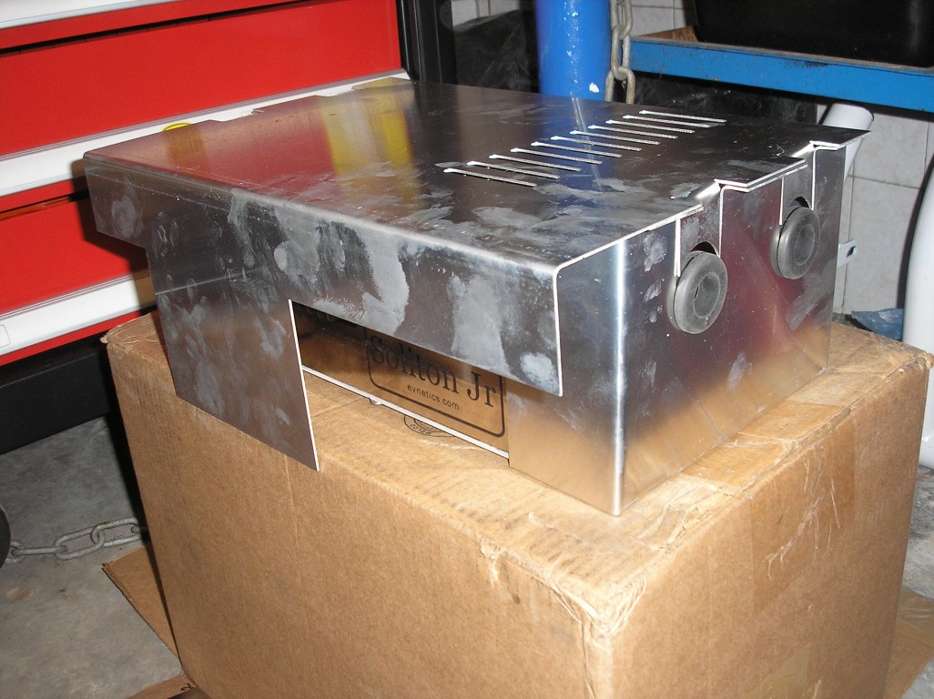
Today I've been busy modifying the controller's enclosure a bit. First a picture of how it looked like originally.
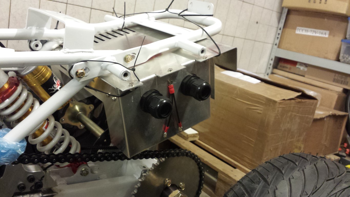
And here what it looks like now.
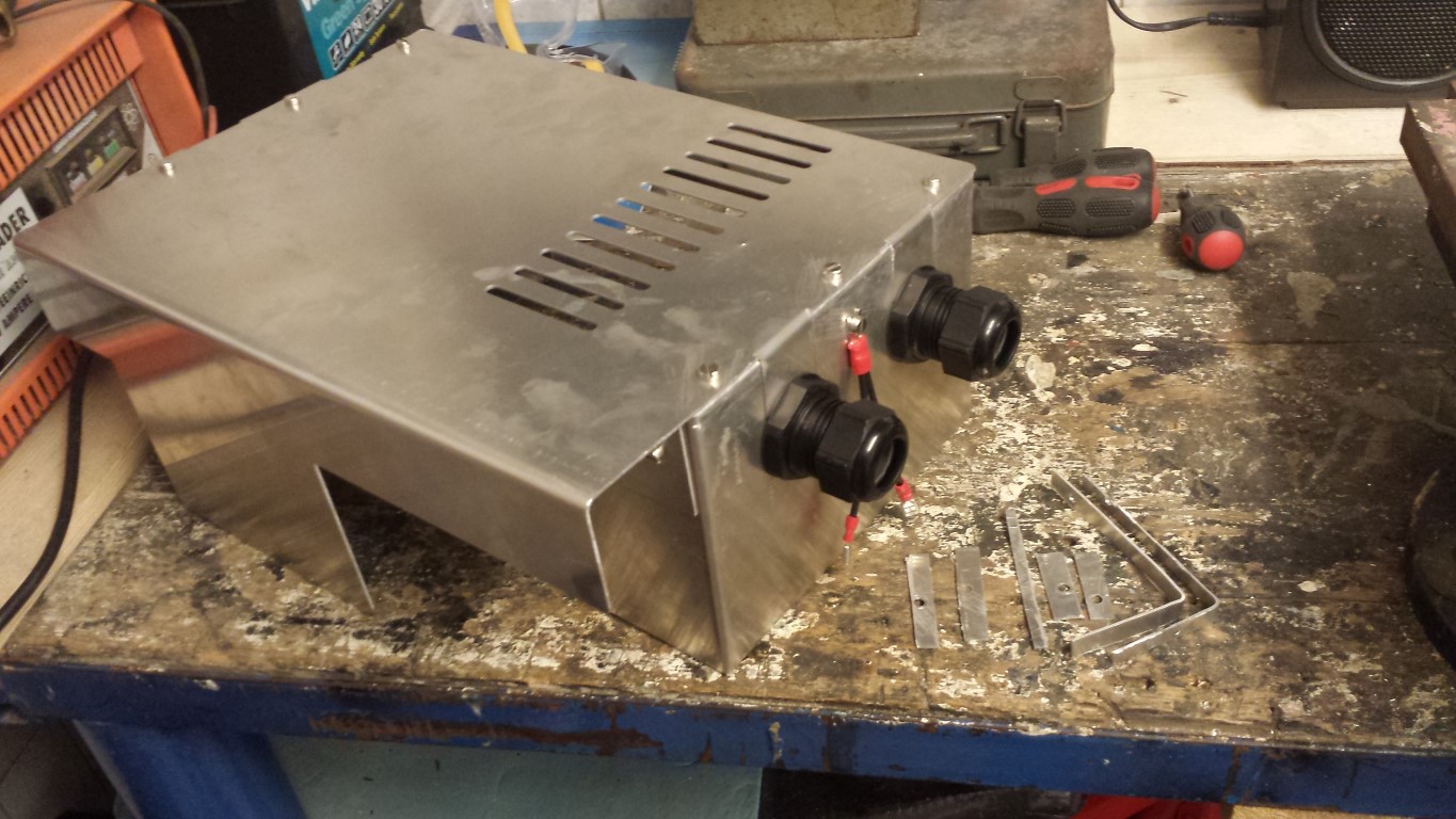
On the sides I bent those outside parts inwards and fitted rivet nuts in there. In all other mounting points I also fitted rivet nuts. I think they're great, already used a lot of them too.
On the top plate I cut off the outer parts and filed them nice and straight. Also filed all of the sharp edges so they're rounded now.
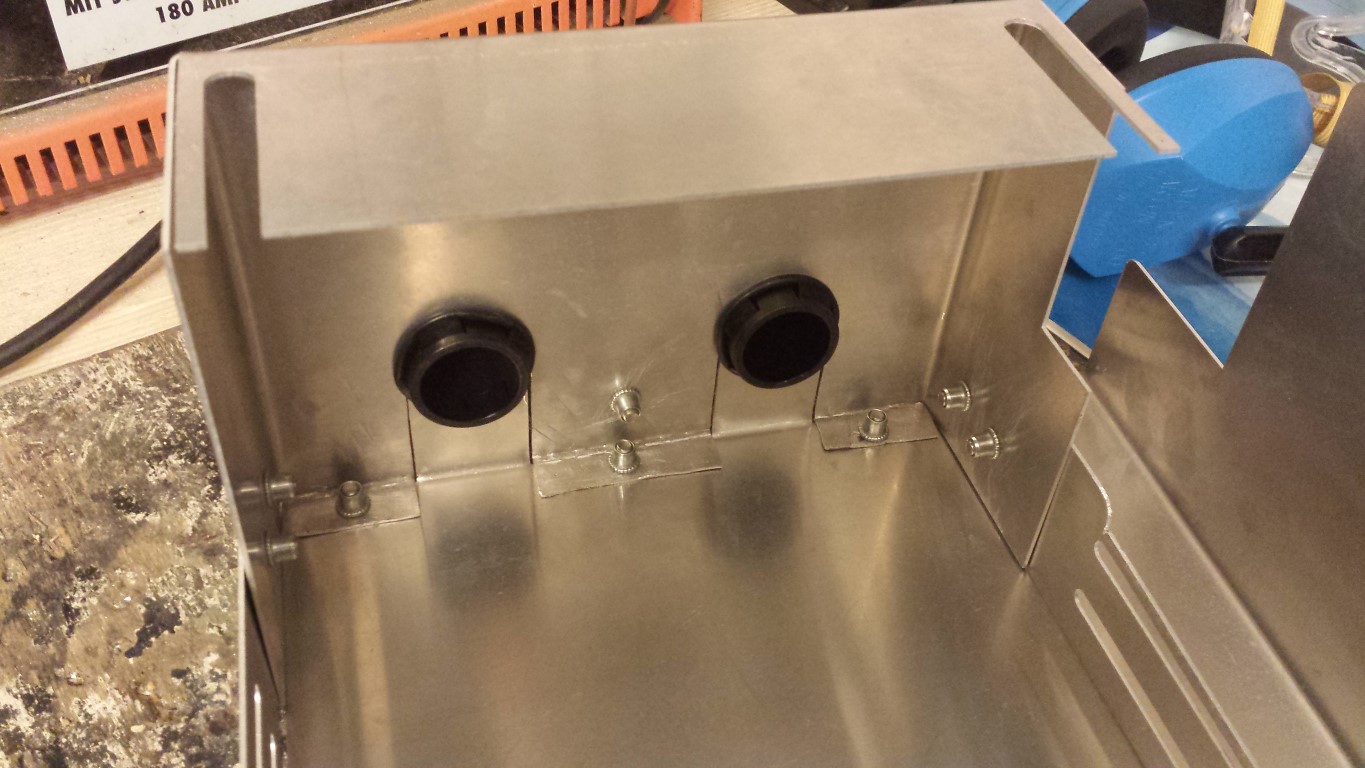
Looks a bit better again and it seems smaller as well now. But what's most important is that I can let the mounts which will be attached to those points where the exhaust silencers used to be just drop down since the enclosure is exactly the same width now.
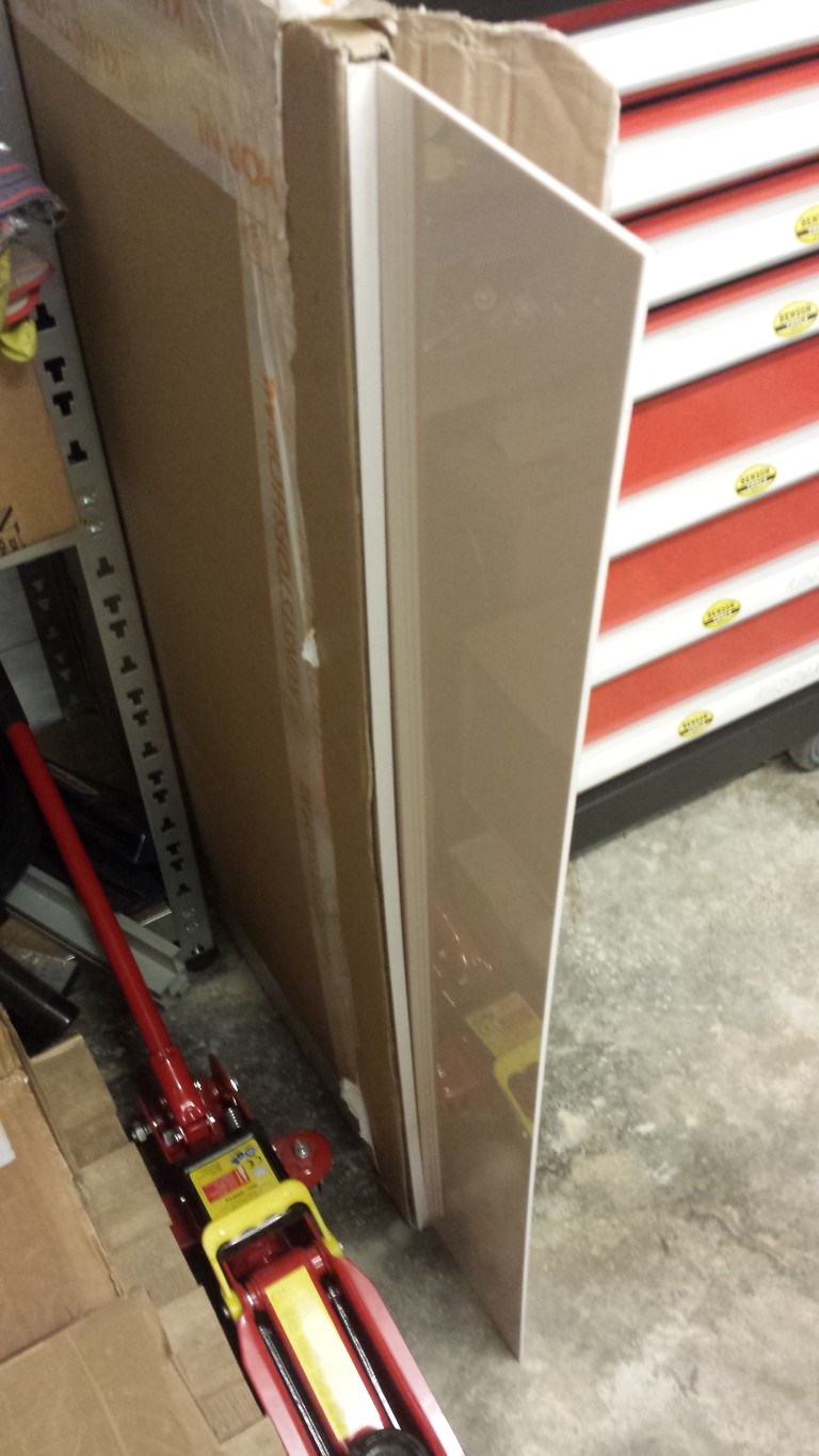
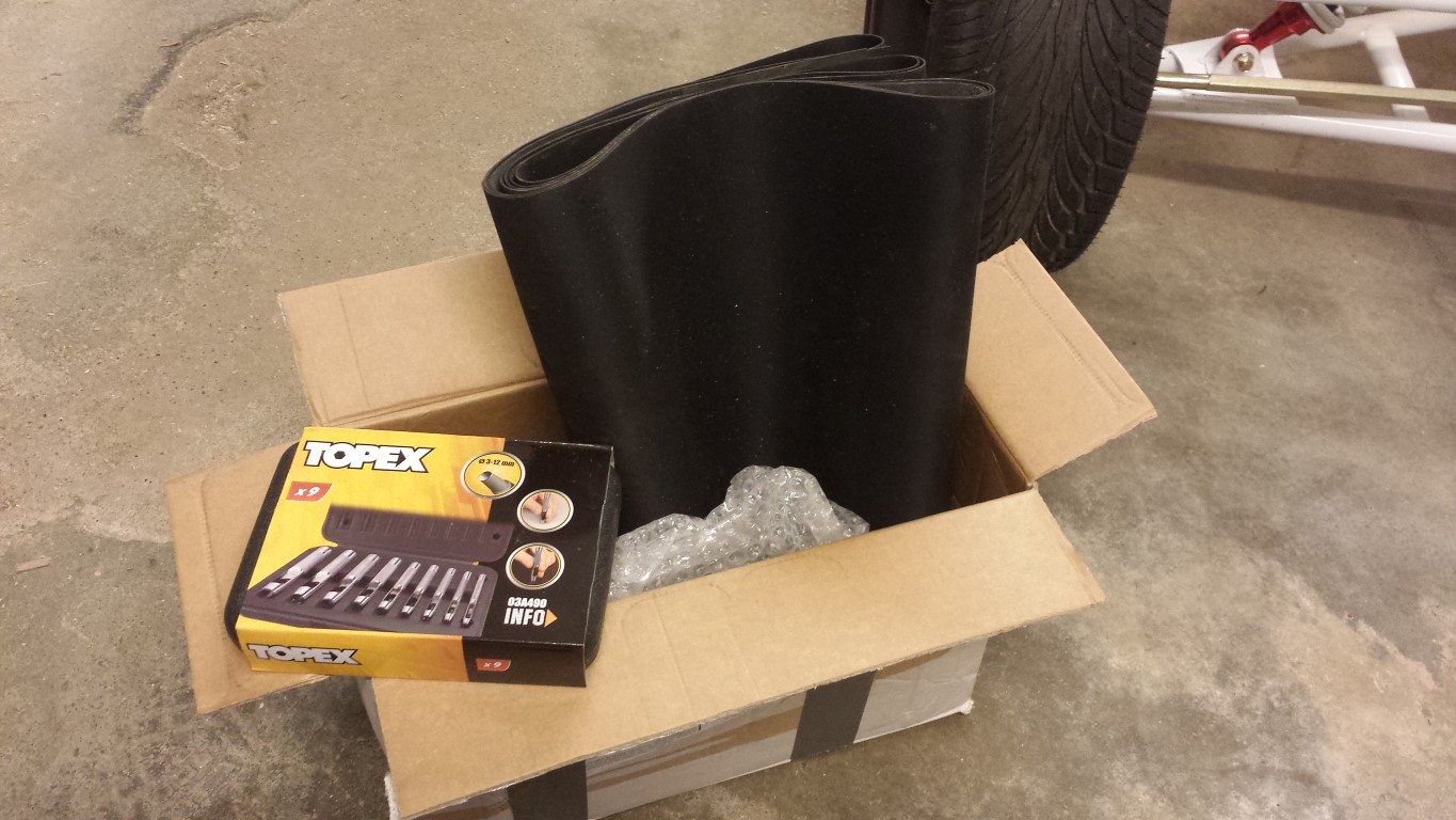
Also received some more parts today. The ABS plates to make the battery boxes, EPDM rubber to make them waterproof and a hole punch set to be able to make some rubber rings.
Posted on 26 May 2013 at 05:23 pm (CET)
Category: Batteries, Controller
Posted on 26 May 2013 at 05:23 pm (CET)
Category: Batteries, Controller
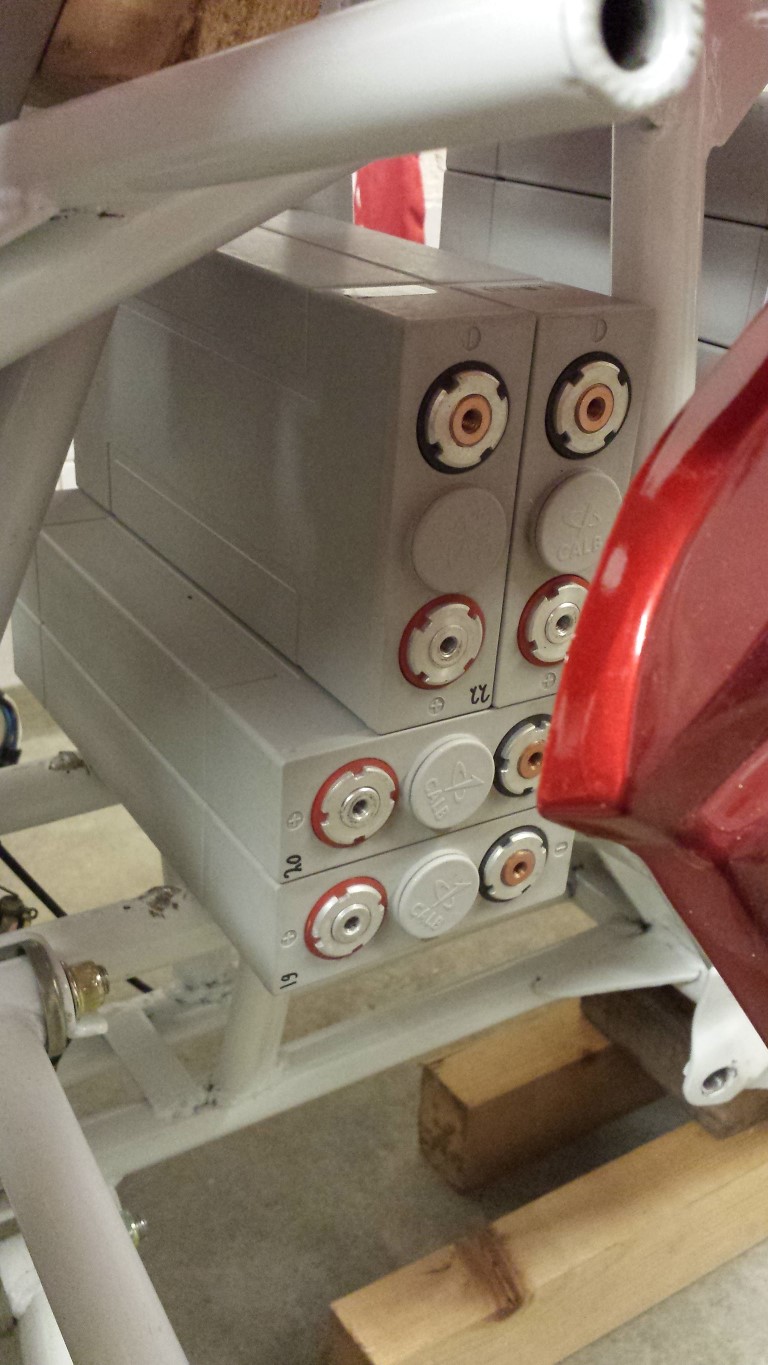
Just tried fitting the batteries, I have good news and bad news.
First the bad news, they don't fit the way I've drawn them.
And then the good news, they fit even better. Instead of 5 battery boxes I will only need 4 since I could still fit 1 more battery where the radiator used to be.
The battery box with just the one battery will no longer be needed which I'm very happy about. I had no idea how to place the cable glands to let the orange cables pass through. On the top and side the frame would be in the way and pointing it towards the ground didn't seem like a good idea either.
So they all fit perfectly and there's still 6 mm of space everywhere as well for the battery boxes to go around the batteries. Here are some pictures again.
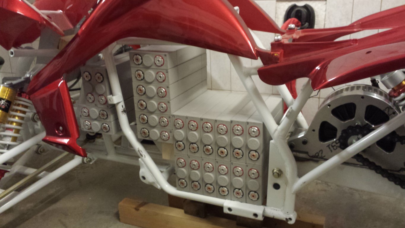
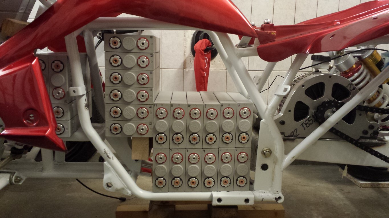
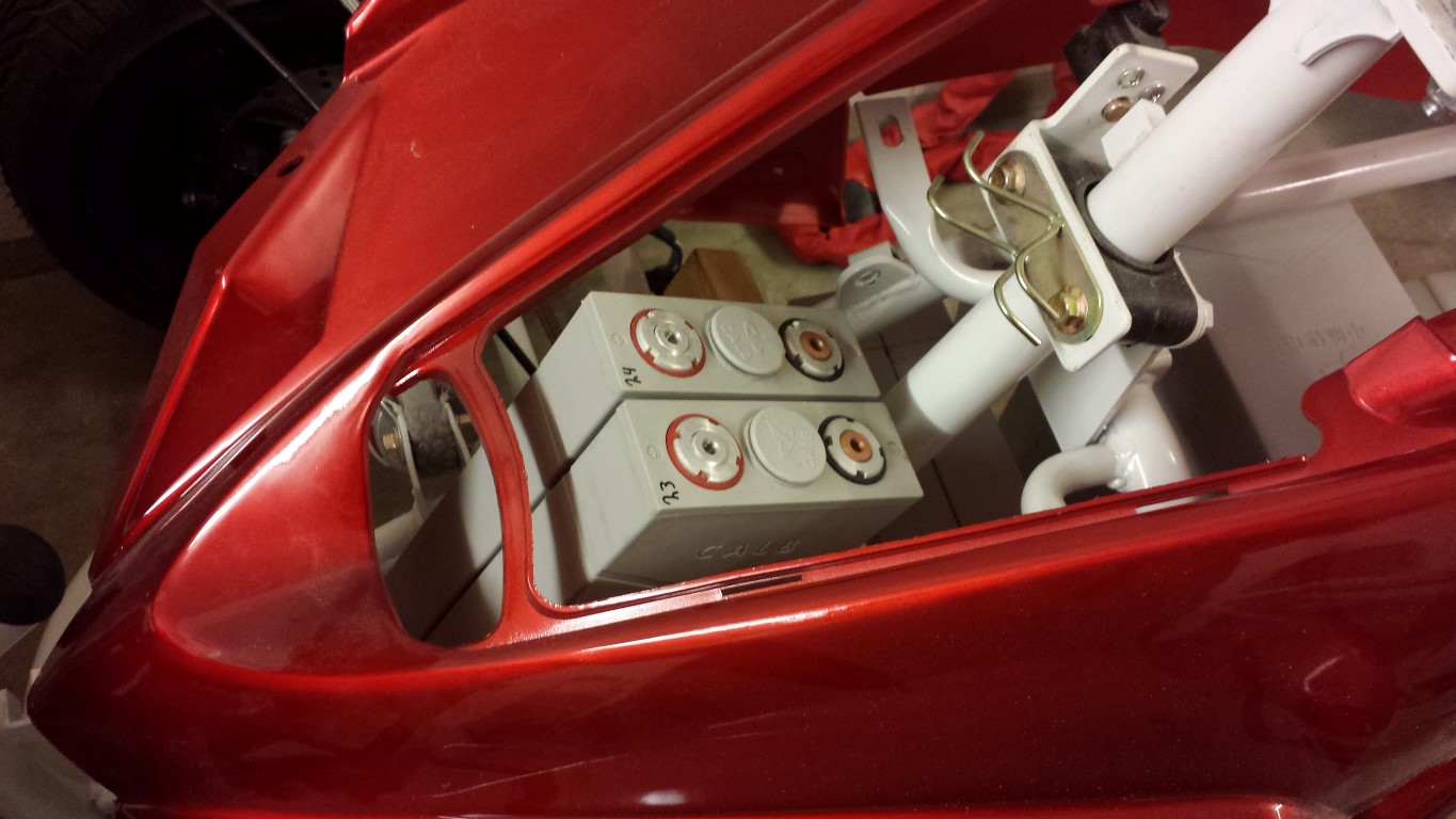
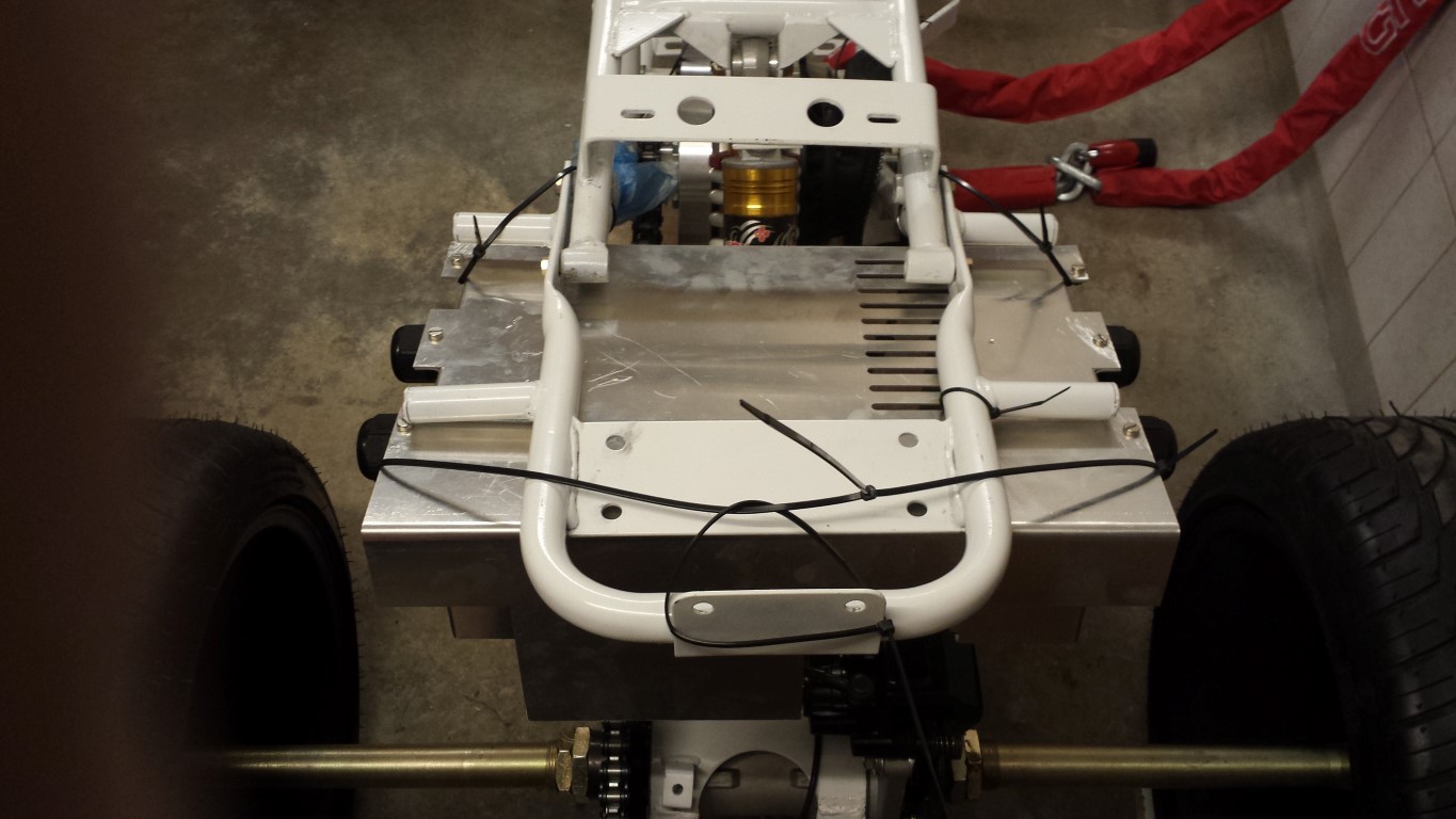
The big empty space in the middle of the frame is where the charger will come and on the sides of it probably some smaller parts of the BMS, display and main fuse.
I also hung up the controller's enclosure with cable ties. I want to have mounts made for this that will come down from those 4 points where the exhaust silencers used the hang from. But I'm not sure yet how I want to have this.
That was it for today.
Posted on 9 March 2013 at 10:06 pm (CET)
Category: Controller, Electric motor
Posted on 9 March 2013 at 10:06 pm (CET)
Category: Controller, Electric motor
Today I made a test setup to check if the controller and motor work well. First I setup the controller on my computer, very easy to do and can't really set anything wrong because of the clear descriptions. I then cut some cables out of the old wire harness, didn't really have anything else to use. To be sure I also added the keyswitch so I could turn it on and off.
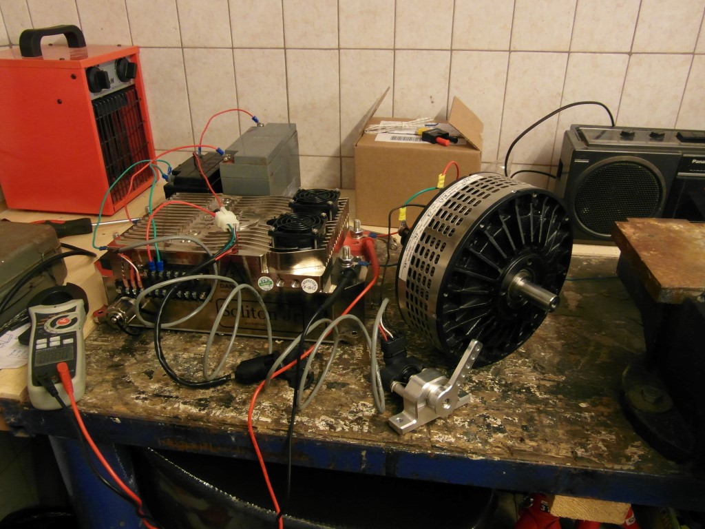
Thankfully everything worked perfectly. Also made a short video so you can see the motor spinning. When turning on the controller you always have to wait before you can control the motor because the capacitors are being charged up. If this wouldn't happen and they directly get high voltage it could damage them. After this is done the contactors (big relais) close, the motor can be controlled and you can 'drive'.
Sorry it's so short, had a bit more footage but something went wrong with filming. By the way, this is with 2 12V batteries in series, so 24V. But in the controller I set a limit for the motor of 13V 10A. Did this because I wasn't sure the small Chinese wires I used would survive with higher voltage and current. But I must say I'm impressed, it was already pretty hard to keep the motor in place with 1 hand when I fully opened the hall sensor, already noticed the torque quite well. I did see 16V going to the motor and 18A so the limit isn't working perfectly. So this was 288W (0,288kW). Still hard to imagine how it'll be like with 25+kW but it's looking good.
Posted on 2 March 2013 at 11:34 pm (CET)
Category: Controller, Parts
Posted on 2 March 2013 at 11:34 pm (CET)
Category: Controller, Parts
Today I received the cable glands from Rebbl. Also still ordered 2 fuses and fuse holders with them for the charger and DC-DC converter.
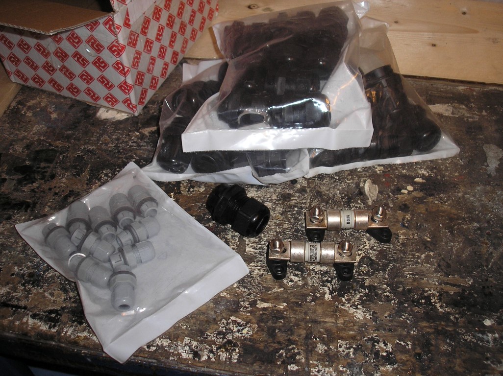
Only a small mistake again, I asked for black cable glands but I received gray for the little ones. No idea how this happened since the bigger ones are black and they were both in the same package. So I'll have to wait and see again if I can trade these for black ones.
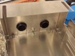
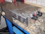
Also started with preparations for the controller enclosure. On the front I shortened it a bit since it was taller than the side parts. Drilled holes to attach everything. Made some cables that will connect to the mesh shield in the orange cables for earthing. Also fitted the cable glands. So this is what it will look like, just have to imagine the orange cables. And there will also be RFI filters on those cables. Then it should be all complete.
Will just still spray the enclosure black, should look at least a bit better then.
Also still have some good news. If all goes well LMC Ltd., where I ordered the motor, should have everything ready for shipping by monday. Might actually get the motor then next week.
The CALB CA60 batteries were also finally ordered, delivery time of approximately 7 weeks now. After that time I should have everything here (if I didn't forget anything) and then I just need to build everything up.

Posted on 3 February 2013 at 12:35 am (CET)
Category: Controller, Parts
Posted on 3 February 2013 at 12:35 am (CET)
Category: Controller, Parts
Today I didn't really do that much, only checked if the real parts fit just as good as the the paper models. And yes it did, still fits well.
Here's a better picture of the controller. On the picture from yesterday you couldn't really tell how big it is.
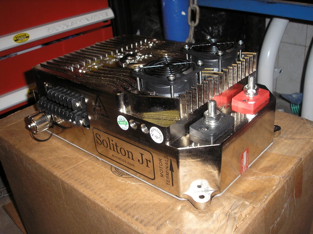
And here with the enclosure around it. Sadly this is mandatory to pass the inspection at the RDW. Can hardly even see the controller anymore.
Still have to drill holes into it to attach everything. It's odd that this hasn't been done yet since this enclosure only fits around this controller. So for everyone who buys one the holes will be in exactly the same spots. It also doesn't look very nice, not everything aligns with eachother (especially the rubbers don't) and they could've cleaned it a bit. Can't really get it off, maybe with some white spirit.
Also had another attempt at the reverse system. I made it like this now.
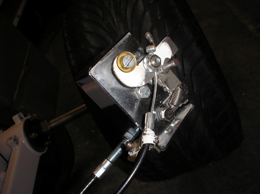
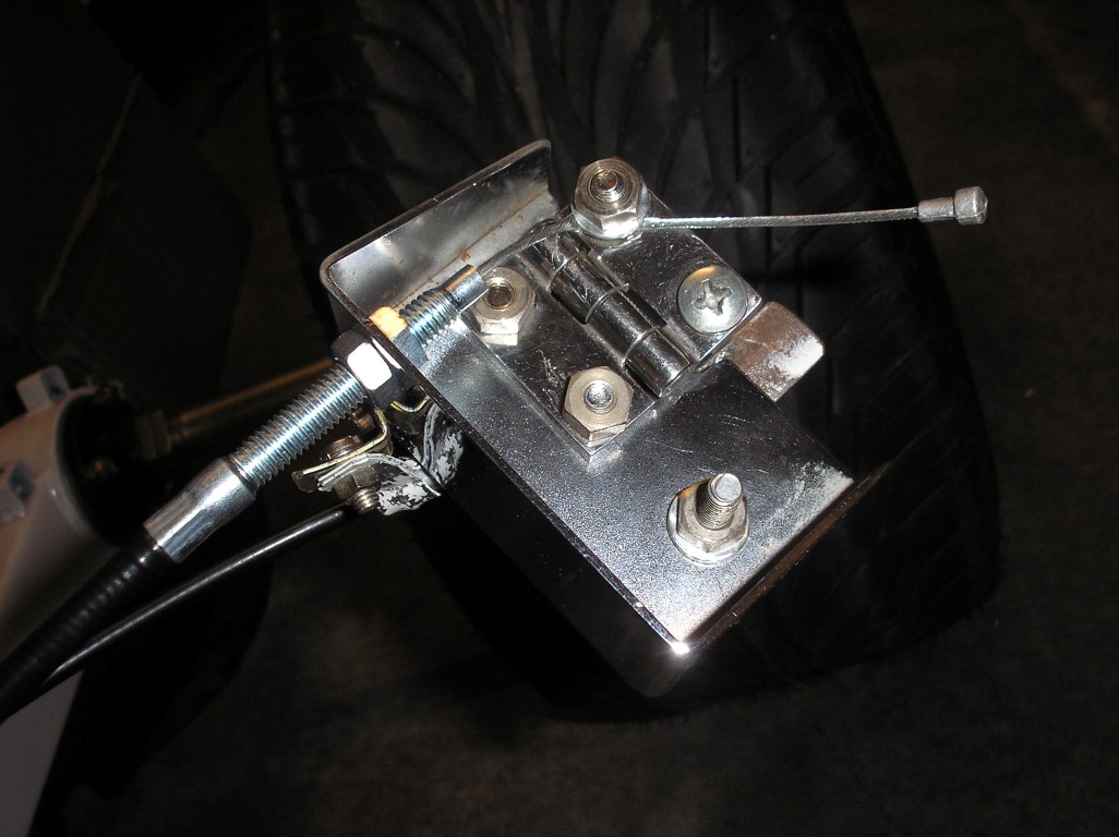
It works.. a little. Still don't think this is really great. Will probably stop to look for a mechanical solution and start looking at something electrical.