
 Nederlands
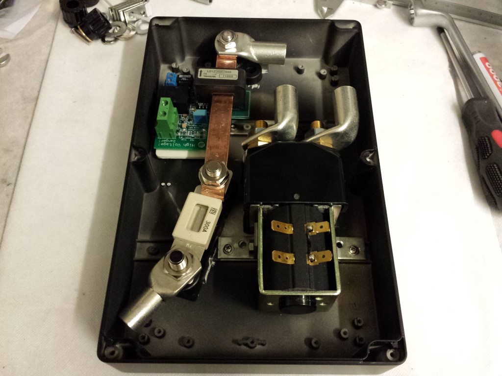
Blog / Bekabeling (HV)
Geplaatst op 7 oktober 2014 om 00:01 u
Categorie: Bekabeling (12V), Bekabeling (HV)
Geplaatst op 7 oktober 2014 om 00:01 u
Categorie: Bekabeling (12V), Bekabeling (HV)
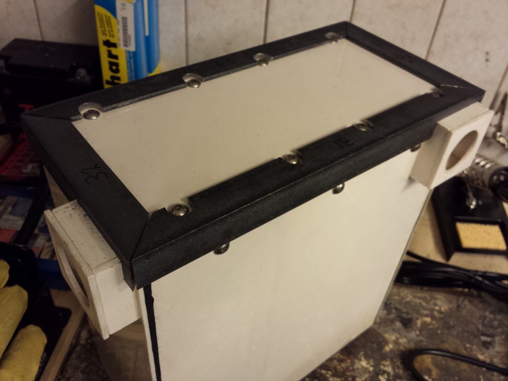
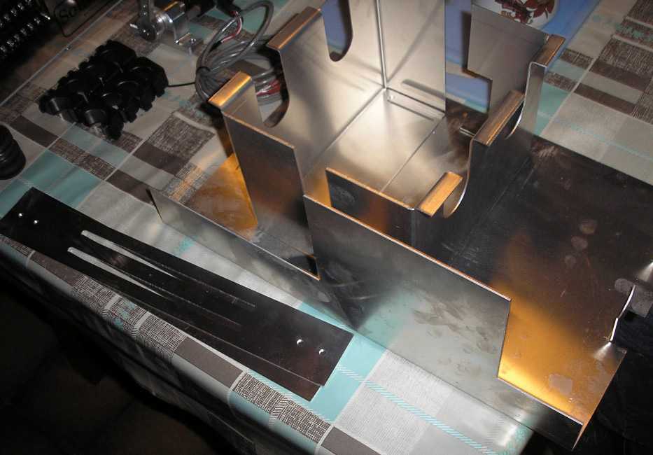
Vanavond de eerste behuizing met hoogspannings componenten klaar gekregen. Hier had ik best wel wat werk aan aangezien de standaard bevestigingspunten niet echt bruikbaar waren en de behuizing ook te laag is om een plaat te maken voor op de bodem. Was ook lastig om te bepalen hoe ik alles wou plaatsen, is nog steeds niet ideaal maar beter dan dit kan ik het ook niet bedenken.
Hierin zitten de main contactor (splitst het accupakket in tweeën om veilig eraan te kunnen werken en voor noodgevallen), sensorplaat voor EV Display (teller) en de hoofdzekering. De oranje kabels moet ik nog aansluiten, doe dit pas als alle behuizingen klaar zijn en in het frame zitten. Heb wel al het 12V gedeelte aangesloten, was niet echt veel werk voor deze behuizing.

Ben ook al begonnen met de laatste behuizing, deze is wat makkelijker en zal ik waarschijnlijk morgen al wel klaar hebben. Ondertussen zijn ook al 15 van de 24 accu's geladen. Dit weekend hoop ik ze dus allemaal te hebben geladen. Dan kan ik ze eindelijk in de behuizingen en in het frame gaan zetten.
Geplaatst op 13 juni 2014 om 01:06 u
Geplaatst op 13 juni 2014 om 01:06 u
Afgelopen dagen bezig geweest om het hele elektrisch schema te tekenen. Ben er nu vrij zeker van dat het allemaal zo aangesloten gaat worden. Alleen die 3 kabels van het Battery Management System weet ik nog niet zeker hoe ik die ga aansluiten. Deze zijn voor het beschikbare vermogen drastisch te verminderen als de accu's leeg zijn zodat je ze niet kunt onderladen. Maar er zal toch nog genoeg vermogen zijn om de quad op een veilige plaats langs de weg te kunnen zetten. Dit kan op meerdere manieren worden aangesloten dus ik wacht daar nog even mee.
Heb ook 2 extra schakelingen erin verwerkt met een aantal knoppen en relais. Die linksboven is voor te kunnen schakelen tussen laag vermogen (Drive Eco), hoog vermogen (Drive Sport) en achteruit (Reverse). En die in het midden is voor het laadproces te starten en stoppen als de laadstekker is aangesloten. Misschien dat ik hier nog een actuator voor haal zodat de laadstekker via deze schakeling ook vergrendeld wordt tijdens het laden.
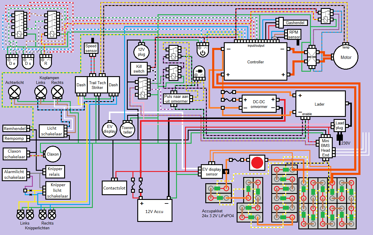
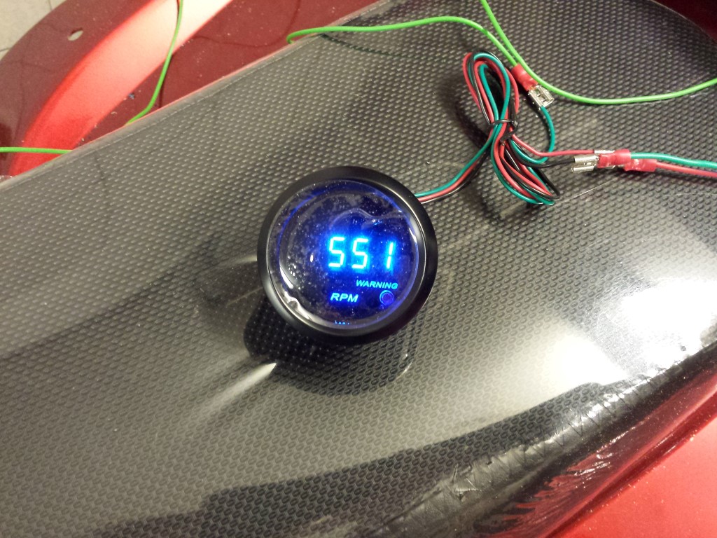
Ook heb ik weer een nieuwe toerenteller, dit keer eentje uit Hong Kong voor 10 euro. En driemaal is scheepsrecht, deze werkt perfect.
Voor de rest ben ik nog bezig met de hoekprofielen aan de kant van de deksels. Moet hier heel wat uitsparingen in maken voor de wartels en boutjes. Ben ik dus nog wel even mee bezig. Maar voor deze accu behuizing zijn ze al helemaal klaar, nog 3 te gaan.
Geplaatst op 1 februari 2013 om 22:30 u
Geplaatst op 1 februari 2013 om 22:30 u
Toen ik vandaag thuis kwam zag ik ineens 3 pakketten, gewicht van 40kg totaal. Wat zou daar toch in zitten?
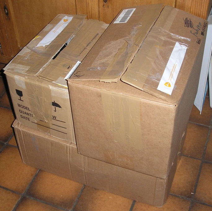
De eerste paar onderdelen voor de ombouw zijn eindelijk hier. Bedankt Rebbl!
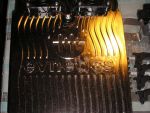
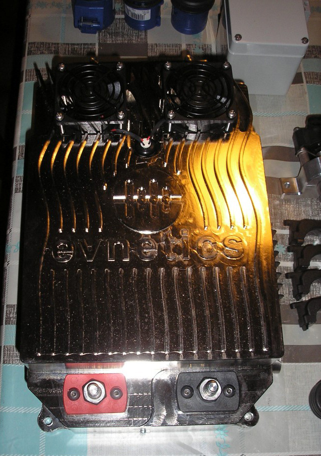
Belangrijkste onderdeel, de Evnetics Soliton Jr controller. Kan veel meer dan nodig is voor dit project maar het is de enige met de juiste certificering om door de keuring van de RDW te komen. Maar het is dan ook wel de beste die je kunt krijgen, erg goede kwaliteit, veel opties en ziet er natuurlijk geweldig uit.
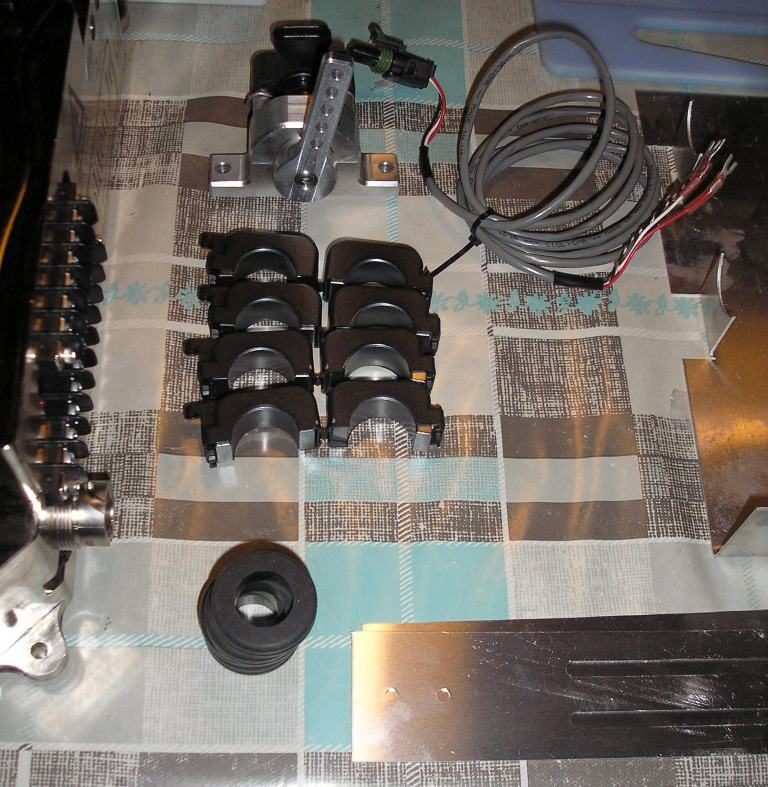
Dan bovenaan de hall sensor, ook van Evnetics dus ook van erg goede kwaliteit. Hier komt de 'gas'kabel op en de hall sensor stuurt dan tussen de 0-5V naar de controller. Daaronder 4 RFI filters en rubbers voor de kabels veilig door de behuizing voor de controller te leiden.
Behuizing voor de controller, bestaat uit een aantal delen. Deze behuizing en de RFI filters (en ook nog een aparte mantel die al in de kabel zelf zit) zijn helaas nodig voor de controller en motor door de RDW keuring te krijgen. Dit vanwege EMC (elektromagnetische compatibiliteit oftewel storing/ruis). Je zult dus niet veel meer zien van de controller zelf wat ik wel jammer vind. Maarja het zal wel moeten, overal in Europa zijn de regels nu zo.
Ook wel belangrijk, de lader voor de accu's op te laden. Deze is al helemaal ingesteld voor de LiFePo4 accu's. Had alleen de gegevens van de CALB SE70's doorgegeven dus hoop dat de instellingen voor de CALB CA60's ook nog goed zijn. Moet dit nog even navragen.
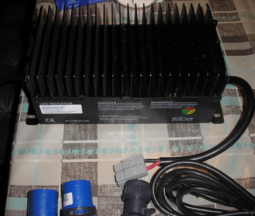
Bovenaan een 150W DC-DC omvormer. Bij elektrische voertuigen is dit er in plaats van de dynamo. Deze zet dus de 72V die ik voor de aandrijving ga gebruiken om naar 12V om de 12V accu geladen te houden.
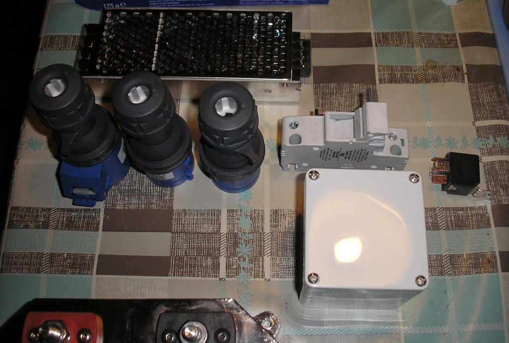
Dan nog de stekkers voor op te laden, een zekering voor de lader en een relais. Alleen geen idee waarom het relais erbij zit, is niet nodig voor zover ik weet. Maargoed deze kan ik toch nog altijd wel gebruiken.
Zit ook nog een doosje bij die volgens mij eigenlijk bedoeld is voor de zekering maar past hier niet eens in. Moet dus even kijken wat ik hiermee ga doen, vind het sowieso maar een rare zekering (je ziet alleen de zekeringhouder, zekering zit erin). Normaal worden hele andere soort zekeringen gebruikt hiervoor.
Dan nog wat kabels.
Deze is voor de laadkabel zelf volgens mij. Moet nog even wat navragen hierover want volgens mij is niet alles compleet voor deze kabel te kunnen maken. De gele rol is een krimpkous.
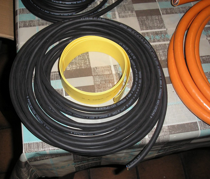
Kabel voor tussen de lader en accu's. Wel fijn dat beide aders zo aan elkaar zitten, makkelijker met bevestigen.
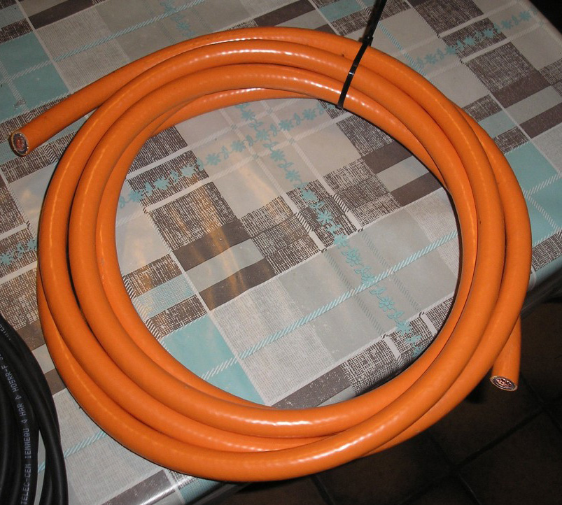
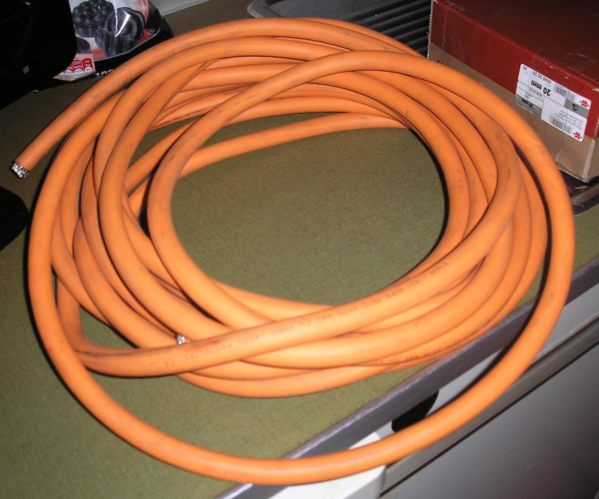
Oranje kabel voor tussen het accupakket en de controller en tussen de controller en motor (met mantel).
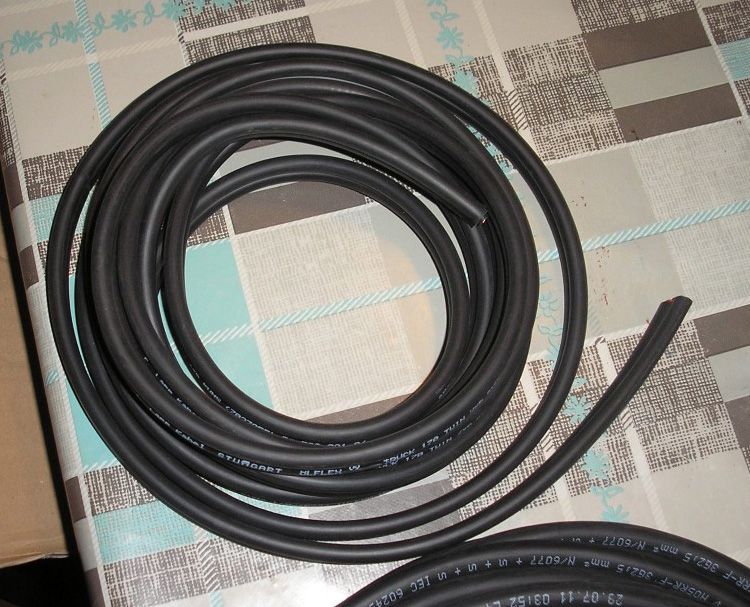
Oranje kabel voor tussen de accupakketten (zonder mantel).
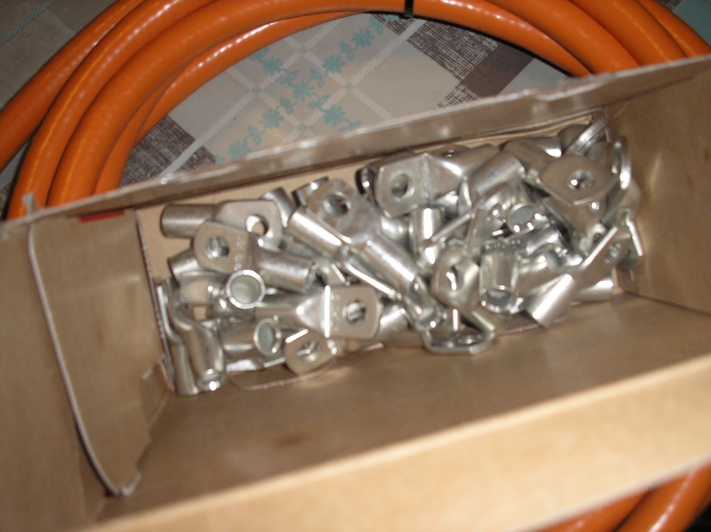
En als laatste kabelschoenen voor de oranje kabels.
Dit is dus nog niet alles, moet het volgende nog krijgen van andere bedrijven:
- Elektromotor (binnen 2-3 weken hopelijk)
- Contactors (grote relais) voor vooruit/achteruit (binnen 2-3 weken hopelijk)
- Noodschakelaar (binnen 2-3 weken hopelijk)
- Accu's (moet nog bestellen, 2 maanden levertijd)
- Aantal zekeringen (moet er nog bestellen)
Heb dus toch al wel veel nu maar moet ook nog steunen voor de controller en motor laten maken. Hierna kan ik pas gaan beginnen met de kabels enzo. Maar kan toch wel weer even vooruit met een aantal dingen totdat de motor hier is.
Geplaatst op 24 december 2012 om 18:13 u
Geplaatst op 24 december 2012 om 18:13 u
Heb het hele elektrisch schema nu af. Komt dus alleen nog wat bij van het BMS maar dat kan ik pas toevoegen als ik het hier heb. Heb nog geen idee hoe dat allemaal aangesloten zal worden.
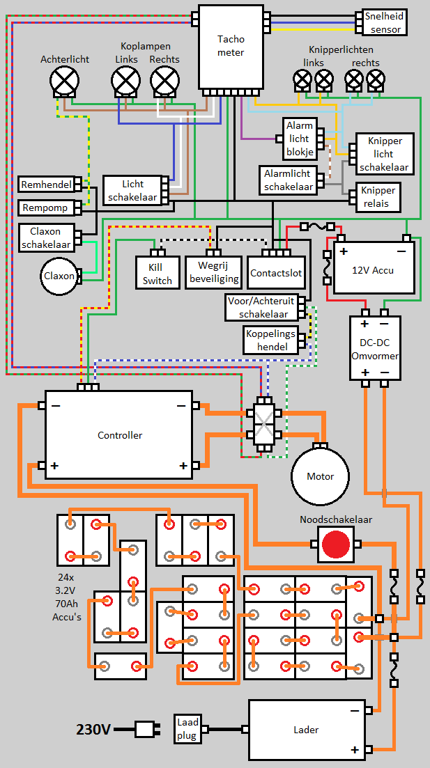
Enige ding wat ik niet zeker weet is van de koppelingshendel. Deze wil ik gebruiken in combinatie met de vooruit/achteruit schakelaar om achteruit te kunnen rijden. Volgens de regels van de RDW moeten hier 2 handelingen voor nodig zijn (of alleen bedienbaar zijn onder de 5km/u maar dit wordt denk ik te ingewikkeld) en dit lijkt me dan de makkelijkste oplossing. Weet alleen niet zeker of het gaat zo, of dat ik op deze manier de controller zal kortsluiten als de schakelaar op achteruit staat en de koppelingshendel niet in wordt gehouden. Zal ik dus even moeten navragen voordat ik het ook echt zo ga aansluiten.